
Dissection by Nicholas Thomas, MD, FRCS
This approach presents:
This approach presents:
- Antero-lateral and postero-lateral neck muscle dissection
- Exposure and transposition of the vertebral artery
- Exposure of the lateral brainstem, cerebellum and the lower cranial nerves
- Craniocervical junction
Postero-lateral neck dissection

Fig. 1. Posterior neck dissection. Superficial muscle layers
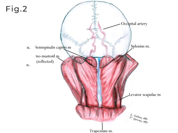
Fig. 2. The trapezius muscle is reflected inferiorly and the sternomastod is partially detached from the mastoid process and reflected anteriorly. The splenius capits and semispinalis capitis muscles are exposed.

Fig. 3. The more deeper middle layer muscles are exposed here. The Sternomastoid and splenius mucles are reflected anteriorly. The longissimus and levator scapulae muslces are exposed. The second and third segments of the occipital artery are presented. The second segment could lie deep or superficial to the longissimus capitis muscle.
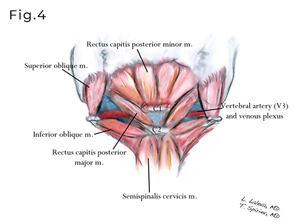
Fig. 4. The suoccipital triangle which is the deepest third layer of the muslces is presented. The triangle is composed of the inferior and superior oblique muscles as well as rectus capitis posterior major muscle. In the depth of this triangle, on the sulcus arteriosus of C1, lies the vertebral artery (V3 segment), surrounded by rich suboccipital venpus plexus.
Posterior neck muscles anatomy


Fig. 5 and 6. Postero-lateral neck dissection. After a lazy “S” incision (see below) the superficial cervical fascia is exposed. The trapezius muscle is dissected and reflected inferiorly.

Fig. 7. After the trapezius muslcle is reflected inferiorly the second layer of muscles is exposed – longissimus, splenius and semispinalis capitis mm.

Fig. 8. The semispinalis capitis and splenius are reflected inferiorly.

Fig. 9. The occipital artery in its second segment is identified deep (could be superficial as variation) to the longissimus.

Fig. 10. The sub-occipital triangle is exposed. C2 transverse process is identified.

Fig. 11. The suboccipital triangle is reflected medially. C1 and vertebral artery are skeletonized.

Fig. 12. The vertebral artery (V3) is fully exposed.

Fig. 13. The transverse foramen of C1 is opened.

Fig. 14. Vertebral artery mobilization.

Fig. 15. C0/C1 joint.

Fig. 16. Drilling of the occipital condyle. Keep it below 50% in order to avoid instability.


Fig. 17 and 18. Craniotomy boudaries.

Fig. 19. Dura incision

Fig. 20. Relevant anatomy
Presenting the VII/VIII n. group and the caudal IX,X,XI n. group. The trigeminal nerve is presented at the cranial and most deeper part of the approach.
Presenting the VII/VIII n. group and the caudal IX,X,XI n. group. The trigeminal nerve is presented at the cranial and most deeper part of the approach.

Fig. 21. The jugular foramen and the hypoglossal canal (supracondylar) are exposed.
Antero-lateral neck muscle anatomy

Fig. 22. Lateral neck dissection. Superficial muscle layer is presented.

Fig. 23. The sterno-mastoid muscle is partially detached from the mastoid process and reflected anteriorly. The splenius muscle is exposed. In the deeper layer a fat tissue with lymphatic elements is reveled. In this plane lies the XI nerve which should be identified and preserved.

Fig. 24. Trapezius and splenius reflected inferiorly. Semispinalis capitis and longissimus capitis are reviled.
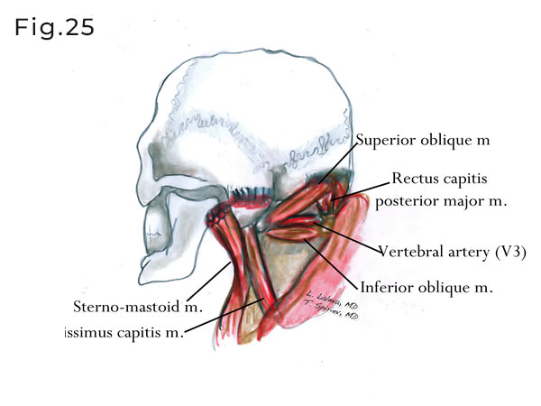
Fig. 25. The suboccipital triangles are exposed after middle muscle layer is reflected inferiorly.

Fig. 26. Skin incision used for antero-lateral neck dissection. The incision starts at the level of thyroid cartilage, continues superiorly on the medial border of the sterno-mastoid muscle and curves posteriorly on the mastoid.

Fig. 27. After the skin incision the sterno-mastoid muscle is exposed.

Fig. 28. The sternomastoid, splenius, semispinalis capitis and longissimus are detached from the mastoid tip and superior nuchal line. The C1 can be palpated just below the mastoid tip. Superior oblique muscle is also identified as part of the suboccipital triangle.

Fig. 29. The accessory nerve could be identified at its exit point at the level of jugular foramen.

Fig. 30. The course of XI nerve could be followed in the fat tissue medial to the sterno- mastoid muscle and the entrance in the mastoid muscle.

Fig. 31. Exposure of the C1 should be performed in subperiosteal manner. Transverse process of C1 should be cleaned from its muscle attachments. V3 segment of the vertebral artery is shown.

Fig. 32. The transverse foramen of C1 is opened and the intraforaminal segment of the VA is shown.

Fig. 33. An illustration revealing the course of the vertebral artery after the transverse foramen of C1 is opened and the intraforaminal segment of the VA exposed.

Fig. 34. Vertebral artery mobilization.

Fig. 35. Image presenting fully mobilized and transposed vertebral artery.

Fig. 36. Illustration presenting the position of C1 and VA transposition. A green ribbon is placed around the VA.

Fig. 37. Illustration presenting the amount of suboccipital bone drilling.

Fig. 38. Occipital condyle drilling. Should be limited below 50% of the condyle mass, in order to avoid instability.

Fig. 39. After the dura is opened a retractor is placed on the lateral cerebellar surface (biventral lobule). The extradural (V3) and the intradural (V4) segments of the vertebral artery are identified.

Fig. 40. After further microsurgical dissection the lower cranial nerves could be identified. Note the long intracranial portion of XI nerve. PICA as a branch of V4 could also be seen here.